Calibration and warping for fulldome projections
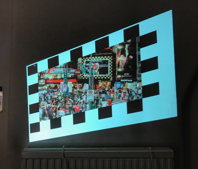
Early test of the warping concept - the projector projects from an extreme angle but, after calibration, the projected photo is straight.
This ongoing project aims to create a suite of tools for easy camera based multi-projector calibration for fulldome type environments. The project specifically intends to support 3D simulation output that needs to be rendered, warped and blended for correct output across multiple overlapping projectors from a single or multiple rendering computers. No projection "server" is required and the simulation software can render directly to the projectors involved therefore ensuring the highest possible image quality.
Although domed projection surfaces are targeted initially, the approach can be used for different shaped surfaces provided the basic geometry of the surface is known.
The approach taken
By taking photos of calibration patterns (such as a typical chessboard pattern) projected onto the dome surface it should be possible to fully understand how the light from each projector falls onto the dome surface. In other words, it should be possible to build a mapping from each screen/projector pixel location to a corresponding 3D position on the dome's surface.
By using a single camera with a fisheye lens placed in the centre of the dome, the maths required to convert from what the camera sees to a physical coordinate becomes a lot simpler. For now, this is the approach I have taken - to assume the use of a single camera with a perfect fisheye lens.
Once we have such a mapping (from projector screen space to physical dome space), we can work backwards to calculate how our simulated scene output should be warped to fit into the area of the dome being projected. This mapping can be represented as a 2D array of coordinates such that each pair of coordinates represents the offset target position for that point on the rendered screen space.
This image warping operation can be inserted as a post-processing for live 3D simulations. For each projector, the scene can be rendered to a buffer from the virtual eye point (for example, the center of the dome) with a model and projection matrix such that the resulting image at least covers the projected dome area. This buffer can then used as a texture to render a mesh of polygons in an orthogonal projection offset to achieve the final warped output image.
Dome simulator
As I don't have easy access to (or enough space to set up) a large hemispherical dome with multiple projectors, I'm building a simulator to acts as fake input for the calibration process and to view the resulting aligned and warped output after calibration.
The simulator is a Cocoa application that lets you define your dome parameters along with a number of projection sources (with position, orientation and FOV parameters adjustable). An HTTP interface allows the "projecting" of screen images via a simple POST request for a particular projector. The simulator then renders the image onto the virtual dome surface as a mesh of polygons. The position of the polygon vertices are calculated by projecting and intersecting lines through the projector's frustum onto the dome surface).
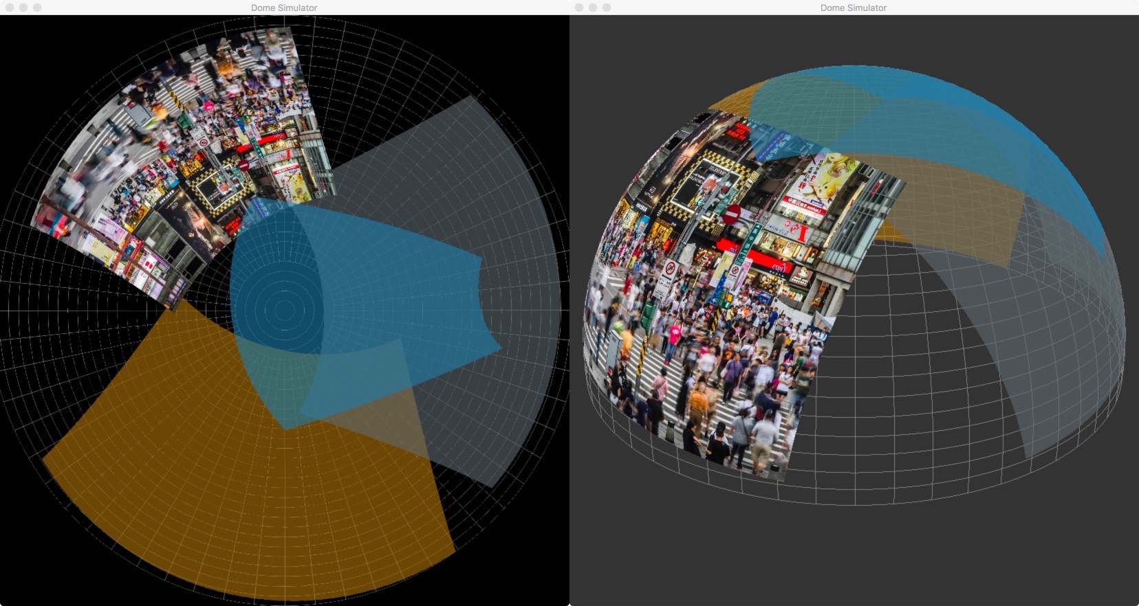
Perspective and fisheye view with four "projected" test images.
Fisheye output from simulator. This simulates the camera image taken during the calibration process.
Calibrator
Four simulated projectors projecting content rendered (then warped) from the virtual eye point
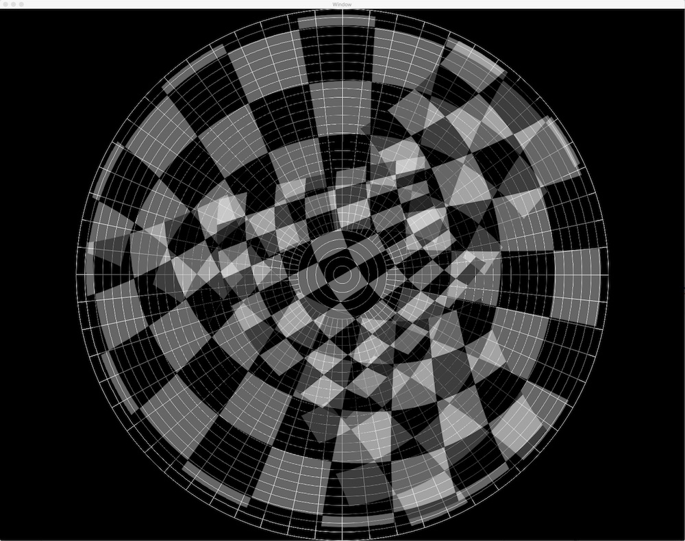
The calibrator application requests fisheye "photos" from the simulator via the embedded HTTP server. It also generates and sends the chessboard calibration pattern to the simulator and calculates a warp for each simulated projector in turn. The approximate pose of the projector and an optimum scene FOV is also calculated based on the eye point. At the moment the eye point is taken to be the center of the dome.
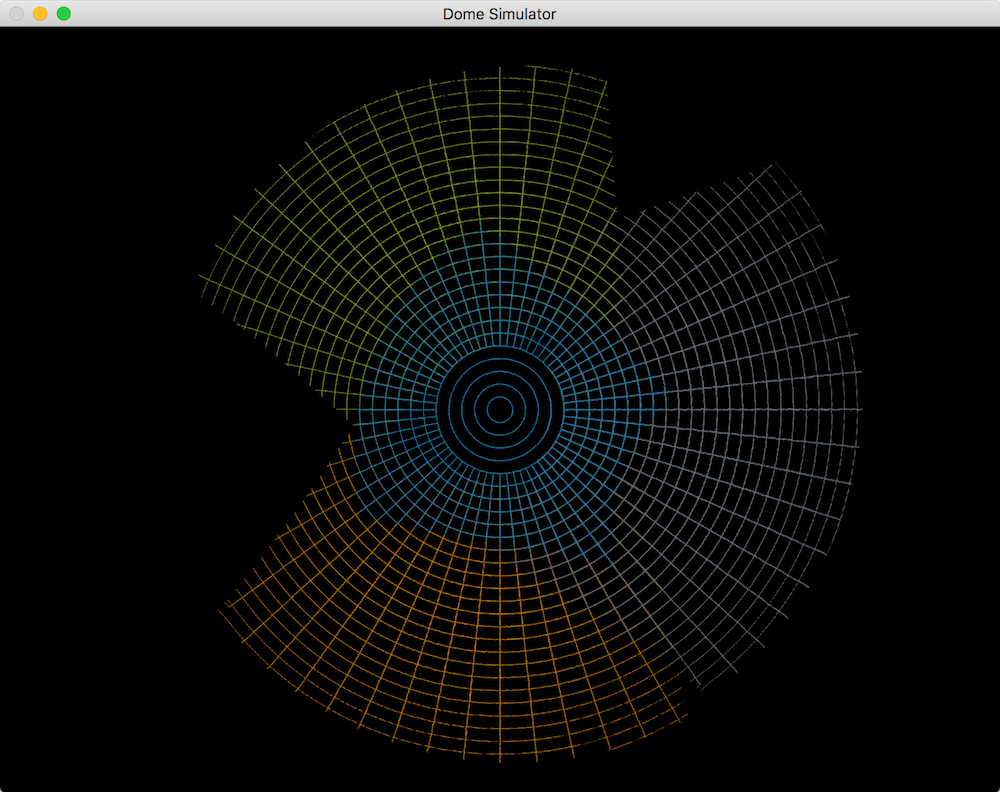
To view the quality of the alignment and warp, the simulator can also render the dome structure but with the modelview and field of view passed back by the calibration process. This modelview matrix has the eye point fixed at the center of the dome sphere and looks in a direction with a FOV large enough to render the part of the scene that will be warped into that projector's part of the dome. The dome rendered in this way should exactly match the known geometry of the dome. Later I will add a more interesting test scene.